How to correctly measure warp on round parts?
When I took my Moldflow Expert exam, I didn’t get every question correct. One area that I did particularly poorly on was measuring warp on round parts. I made it my mission to understand how to correctly measure warp on round parts, which brings us to today’s topic!
There are multiple ways to measure roundness or concentricity within Moldflow Insight:
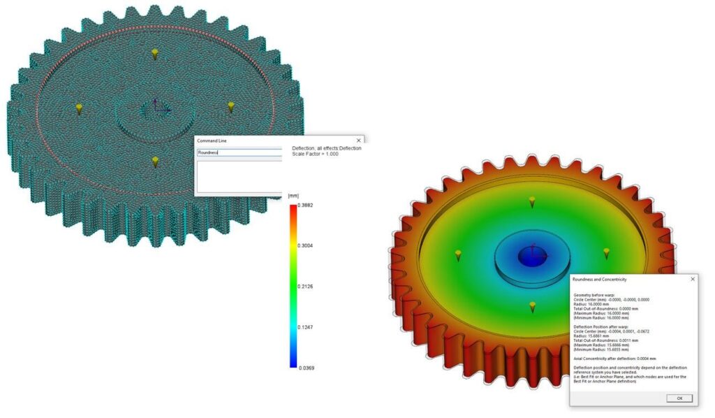
Roundness Script – Run a Warp analysis, select a circular node list that you wish to measure, then open the Command Line and type “Roundness”
Radial Deflection Plot – ensure that your part is centered about the origin or create a Local Coordinate System (LCS) at the center of your circular feature, run Warp analysis then modify or create a new Deflection All Effect plot. Go to the Deflection tab and change the Magnitude/Component to Radial, choose the correct coordinate system, and select Cylindrical system type.
Depending on the feature you a measuring, you may also need to go to the Results tab – Warpage panel – Visualize – Best Fit and select a nodes list is that concentric to the round feature you are measuring
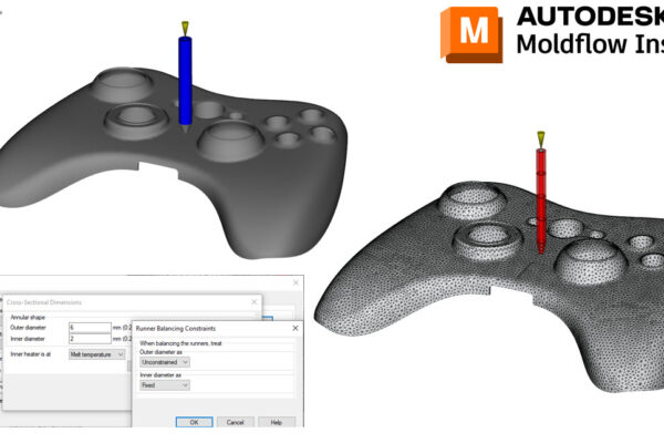
Radial Path Plot – Run a Warp analysis then select/save a node list for your path plot. I usually copy the node list at this step too. Create a new Deflection – Path Plot and paste your node list. You can then go to plot properties and select Radial Component, pick your LCS as well as pick Cylindrical type
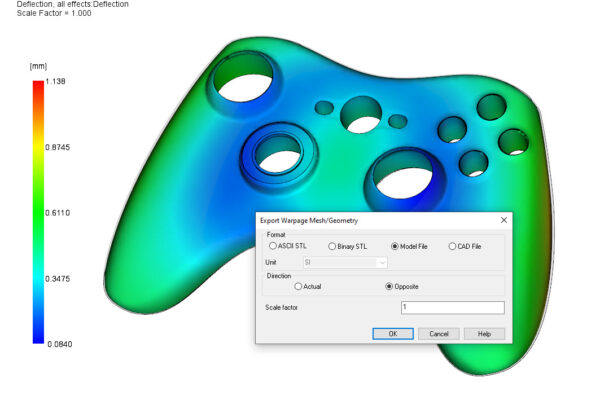
Bonus Tip – you can also export the XY path plot from Moldflow into excel for further plotting!
How do you measure Roundness in Moldflow?
Thanks everyone for all the comments, likes, shares, and direct messages on my Moldflow Monday posts.