Why to mesh as a Dual Domain Mesh first?
When I was learning Moldflow almost 20 years ago, I was taught to mesh everything as a Dual Domain mesh first (actually Dual Domain was called Fusion mesh back then). I still mesh that same way for several reasons:
- It’s easier to clean up 2 surface layers of a Dual Domain mesh than 10 tetrahedral layers on a 3D mesh.
- I run Molding Window on most of my parts which is a Midplane or Dual Domain only analysis.
- I use my Dual Domain Mesh Statistics to determine if I should stay in Dual Domain or go to 3D.
- I see a lot of different CAD types from different customers so I am always worried about CAD cleanliness
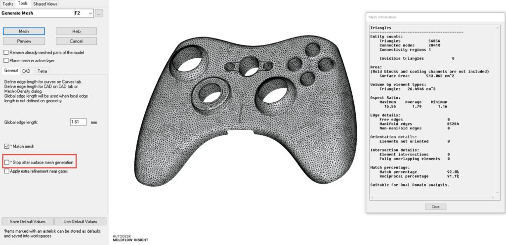
You can mesh right to 3D and if you have clean CAD, the default mesher will probably work fine. Meshing directly to 3D even has an option to “Stop after surface mesh generation”.
If I am using Midplane, I will also create my Midplane mesh from my clean Dual Domain mesh.
What mesh types to use for simulations?
Finite element meshes are an essential to run process simulations like the injection molding simulations in Moldflow as well as mechanical simulations. These simulations allow for predicting and evaluating the feasibility of product design, material distribution, and structural stiffness. There are different types of finite element meshes in Moldflow, including DualDomain meshes, 3D meshes, and Midplane meshes.
When should I use DualDomain meshes?
DualDomain meshes represent surface elements to simulate material distribution and flow behavior in plastic parts. Surface elements can more accurately capture deformation and stress distribution in thinner areas such as edges and corners. Combining both elements consecutively results in more accurate predictions of the injection molding process and better identification of potential issues like material accumulations and air traps, .
When should I use 3D meshes?
3D meshes use volumetric elements to simulate material distribution and flow behavior in plastic parts. Unlike 2D meshes that only capture the flow direction in the plane of the plate, 3D meshes can also capture the flow direction in the depth of the part. This enables more accurate predictions of the injection molding process and better identification of issues like warpage and shrinkage.
When should I use Midplane meshes?
Midplane meshes are another type of meshing technique used in injection molding simulations with Moldflow. These meshes divide the 3D model into two halves along the centerline, creating two mirrored surfaces or midplanes. The midplane meshing technique may be used when the part geometry is symmetric, allowing for the creation of a more efficient mesh and reducing the computational time required for the simulation. Also it’s sometimes being used for very large and complex parts such as instrument panels or front or back bumpers on automobiles.
Here are some reasons why Midplane meshes are used in injection molding simulations:
- Efficiency: Midplane meshes can sometimes be created more quickly than other meshing techniques. Much more importantly they lead to significant time savings with regard to computing time, as the overall number of finite elements is being reduced drastically.
- Symmetry: Midplane meshes are ideal for parts that have a high degree of symmetry. Because the mesh is mirrored along the centerline, the simulation can take advantage of this symmetry to reduce the complexity of the model and the amount of computation required.
- Accuracy: Midplane meshes can provide accurate results for symmetric parts, and can also be used for non-symmetric parts with some modifications to the mesh.
- Storage space: Midplane meshes require less storage space compared to other meshing techniques. This is because only half of the geometry needs to be stored in memory, which can be helpful for large or complex simulations.
To learn more about this topic and many more in Moldflow, check out our trainings which we offer online or in person. By acquiring Moldflow licenses via MFS you may also gain access to our in person phone and mail support. In case you need any more details, please contact us via our contact formular.
How do you mesh in Moldflow Insight?


