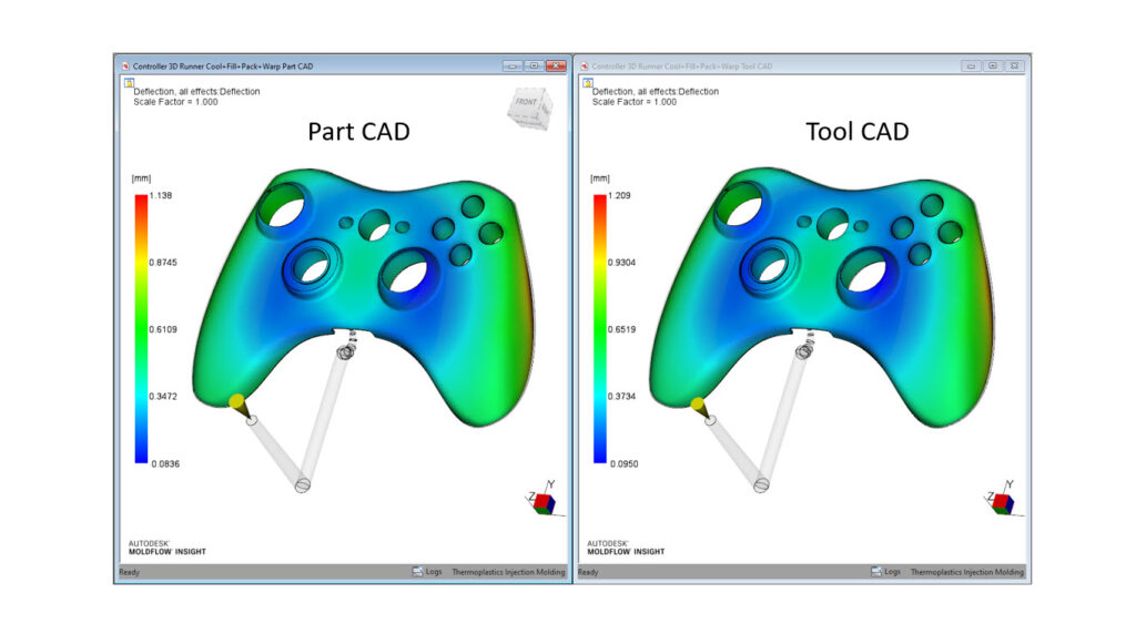
Part CAD vs Tool CAD – what’s the difference and which one should we be using in Moldflow?
Part CAD – We would define this as the desired or designed molded part shape and size. Typically this would be the starting point for our simulation work.
Tool CAD – We would define this model as the grown, or larger, CAD that would represent the tool negative. We would use the shrink rates to increase the size of the Part CAD to generate this model. Ultimately, the Tool CAD would be used to cut the mold cavity.
We think the best approach would be to start with Part CAD to answer early questions like gate location, runner size, and processing conditions. Once cooling is added and shrink rates have been established, your final simulation should probably be using Tool CAD.
If you are trying to match deflection from actual molded samples, simulating the Tool CAD would give you the most accurate comparison.
Do you use Part CAD or Tool CAD in your Moldflow simulations?